A trip through the Graphics Pipeline 2011, part 4
This post is part of the series “A trip through the Graphics Pipeline 2011”.
Welcome back. Last part was about vertex shaders, with some coverage of GPU shader units in general. Mostly, they’re just vector processors, but they have access to one resource that doesn’t exist in other vector architectures: Texture samplers. They’re an integral part of the GPU pipeline and are complicated (and interesting!) enough to warrant their own article, so here goes.
Texture state
Before we start with the actual texturing operations, let’s have a look at the API state that drives texturing. In the D3D11 part, this is composed of 3 distinct parts:
- The sampler state. Filter mode, addressing mode, max anisotropy, stuff like that. This controls how texture sampling is done in a general way.
- The underlying texture resource. This boils down to a pointer to the raw texture bits in memory. The resource also determines whether it’s a single texture or a texture array, what multisample format the texture has (if any), and the physical layout of the texture bits – i.e. at the resource level, it’s not yet decided how the values in memory are to be interpreted exactly, but their memory layout is nailed down.
- The shader resource view (SRV for short). This determines how the texture bits are to be interpreted by the sampler. In D3D10+, the resource view links to the underlying resource, so you never specify the resource explicitly.
Most of the time, you will create a texture resource with a given format, let’s say RGBA, 8 bits per component, and then just create a matching SRV. But you can also create a texture as “8 bits per component, typeless” and then have several different SRVs for the same resource that read the underlying data in different formats, e.g. once as UNORM8_SRGB (unsigned 8-bit value in sRGB space that gets mapped to float 0..1) and once as UINT8 (unsigned 8-bit integer).
Creating the extra SRV seems like an annoying extra step at first, but the point is that this allows the API runtime to do all type checking at SRV creation time; if you get a valid SRV back, that means the SRV and resource formats are compatible, and no further type checking needs to be done while that SRV exists. In other words, it’s all about API efficiency here.
Anyway, at the hardware level, what this boils down to is just a bag of state associated with a texture sampling operation – sampler state, texture/format to use, etc. – that needs to get kept somewhere (see part 2 for an explanation of various ways to manage state in a pipelined architecture). So again, there’s various methods, from “pipeline flush every time any state changes” to “just go completely stateless in the sampler and send the full set along with every texture request”, with various options inbetween. It’s nothing you need to worry about – this is the kind of thing where HW architects whip up a cost-benefit analysis, simulate a few workloads and then take whichever method comes out ahead – but it’s worth repeating: as PC programmer, don’t assume the HW adheres to any particular model.
Don’t assume that texture switches are expensive – they might be fully pipelined with stateless texture samplers so they’re basically free. But don’t assume they’re completely free either – maybe they are not fully pipelined or there’s a cap on the maximum number of different sets of texture states in the pipeline at any given time. Unless you’re on a console with fixed hardware (or you hand-optimize your engine for every generation of graphics HW you’re targeting), there’s just no way to tell. So when optimizing, do the obvious stuff – sort by material where possible to avoid unnecessary state changes and the like – which certainly saves you some API work at the very least, and then leave it at that. Don’t do anything fancy based on any particular model of what the HW is doing, because it can (and will!) change in the blink of an eye between HW generations.
Anatomy of a texture request
So, how much information do we need to send along with a texture sample request? It depends on the texture type and which kind of sampling instruction we’re using. For now, let’s assume a 2D texture. What information do we need to send if we want to do a 2D texture sample with, say, up to 4x anisotropic sampling?
- The 2D texture coordinates – 2 floats, and sticking with the D3D terminology in this series, I’m going to call them u/v and not s/t.
- The partial derivatives of u and v along the screen “x” direction:
,
.
- Similarly, we need the partial derivative in the “y” direction too:
,
.
So, that’s 6 floats for a fairly pedestrian 2D sampling request (of the SampleGrad variety) – probably more than you thought. The 4 gradient values are used both for mipmap selection and to choose the size and shape of the anisotropic filtering kernel. You can also use texture sampling instructions that explicitly specify a mipmap level (in HLSL, that would be SampleLevel) – these don’t need the gradients, just a single value containing the LOD parameter, but they also can’t do anisotropic filtering – the best you’ll get is trilinear! Anyway, let’s stay with those 6 floats for a while. That sure seems like a lot. Do we really need to send them along with every texture request?
The answer is: depends. In everything but Pixel Shaders, the answer is yes, we really have to (if we want anisotropic filtering that is). In Pixel Shaders, turns out we don’t; there’s a trick that allows Pixel Shaders to give you gradient instructions (where you can compute some value and then ask the hardware “what is the approximate screen-space gradient of this value?”), and that same trick can be employed by the texture sampler to get all the required partial derivatives just from the coordinates. So for a PS 2D “sample” instruction, you really only need to send the 2 coordinates which imply the rest, provided you’re willing to do some more math in the sampler units.
Just for kicks: What’s the worst-case number of parameters required for a single texture sample? In the current D3D11 pipeline, it’s a SampleGrad on a Cubemap array. Let’s see the tally:
- 3D texture coordinates – u, v, w: 3 floats.
- Cubemap array index: one int (let’s just bill that at the same cost as a float here).
- Gradient of (u,v,w) in the screen x and y directions: 6 floats.
For a total of 10 values per pixel sampled – that’s 40 bytes if you actually store it like that. Now, you might decide that you don’t need full 32 bits for all of this (it’s probably overkill for the array index and gradients), but it’s still a lot of data to be sending around.
In fact, let’s check what kind of bandwidth we’re talking about here. Let’s assume that most of our textures are 2D (with a few cubemaps thrown in), that most of our texture sampling requests come from the Pixel Shader with little to no texture samples in the Vertex Shader, and that the regular Sample-type requests are the most frequent, followed by SampleLevel (all of this is pretty typical for actual rendering you see in games). That means the average number of 32-bit floats values sent per pixel will be somewhere between 2 (u+v) and 3 (u+v+w / u+v+lod), let’s say 2.5, or 10 bytes.
Assume a medium resolution – say, 1280×720, which is about 0.92 million pixels. How many texture samples does your average game pixel shader have? I’d say at least 3. Let’s say we have a modest amount of overdraw, so during the 3D rendering phase, we touch each pixel on the screen roughly twice. And then we finish it off with a few texture-heavy full-screen passes to do post-processing. That probably adds at least another 6 samples per pixel, taking into account that some of that postprocessing will be done at a lower resolution. Add it all up and we have 0.92 * (3*2 + 6) = about 11 million texture samples per frame, which at 30 fps is about 330 million a second. At 10 bytes per request, that’s 3.3 GB/s just for texture request payloads. Lower bound, since there’s some extra overhead involved (we’ll get to that in a second). Note that I’m *cough* erring “a bit” on the low side with all of these numbers :). An actual modern game on a good DX11 card will run in significantly higher resolution, with more complex shaders than I listed, comparable amount of overdraw or even somewhat less (deferred shading/lighting to the rescue!), higher frame rate, and way more complex postprocessing – go ahead, do a quick back-of-the-envelope calculation how much texture request bandwidth a decent-quality SSAO pass in quarter-resolution with bilateral upsampling takes…
Point being, this whole texture bandwidth thing is not something you can just hand-wave away. The texture samplers aren’t part of the shader cores, they’re separate units some distance away on the chip, and shuffling multiple gigabytes per second around isn’t something that just happens by itself. This is an actual architectural issue – and it’s a good thing we don’t use SampleGrad on Cubemap arrays for everything :)
But who asks for a single texture sample?
The answer is of course: No one. Our texture requests are coming from shader units, which we know process somewhere between 16 and 64 pixels / vertices / control points / … at once. So our shaders won’t be sending individual texture samples, they’ll dispatch a bunch of them at once. This time, I’ll use 16 as the number – simply because the 32 I chose last time is non-square, which just seems weird when talking about 2D texture requests. So, 16 texture requests at once – build that texture request payload, add some command fields at the start so the sampler knows what to do, add some more fields so the sampler knows which texture and sampler state to use (again, see the remarks above on state), and send that off to a texture sampler somewhere.
This will take a while.
No, seriously. Texture samplers have a seriously long pipeline (we’ll soon see why); a texture sampling operation takes way too long for a shader unit to just sit idle for all that time. Again, say it with me: throughput. So what happens is that on a texture sample, a shader unit will just quietly switch to another thread/batch and do some other work, then switch back a while later when the results are there. Works just fine as long as there’s enough independent work for the shader units to do!
And once the texture coordinates arrive…
Well, there’s a bunch of computations to be done first: (In here and the following, I’m assuming a simple bilinear sample; trilinear and anisotropic take some more work, see below).
- If this is a
SampleorSampleBias-type request, calculate texture coordinate gradients first. - If no explicit mip level was given, calculate the mip level to be sampled from the gradients and add the LOD bias if specified.
- For each resulting sample position, apply the address modes (wrap / clamp / mirror etc.) to get the right position in the texture to sample from, in normalized [0,1] coordinates.
- If this is a cubemap, we also need to determine which cube face to sample from (based on the absolute values and signs of the u/v/w coordinates), and do a division to project the coordinates onto the unit cube so they are in the [-1,1] interval. We also need to drop one of the 3 coordinates (based on the cube face) and scale/bias the other 2 so they’re in the same [0,1] normalized coordinate space we have for regular texture samples.
- Next, take the [0,1] normalized coordinates and convert them into fixed-point pixel coordinates to sample from – we need some fractional bits for the bilinear interpolation.
- Finally, from the integer x/y/z and texture array index, we can now compute the address to read texels from. Hey, at this point, what’s a few more multiplies and adds among friends?
If you think it sounds bad summed up like that, let me take remind you that this is a simplified view. The above summary doesn’t even cover fun issues such as texture borders or sampling cubemap edges/corners. Trust me, it may sound bad now, but if you were to actually write out the code for everything that needs to happen here, you’d be positively horrified. Good thing we have dedicated hardware to do it for us. :) Anyway, we now have a memory address to get data from. And wherever there’s memory addresses, there’s a cache or two nearby.
Texture cache
Everyone seems to be using a two-level texture cache these days. The second-level cache is a completely bog-standard cache that happens to cache memory containing texture data. The first-level cache is not quite as standard, because it’s got additional smarts. It’s also smaller than you probably expect – on the order of 4-8kb per sampler. Let’s cover the size first, because it tends to come as a surprise to most people.
The thing is this: Most texture sampling is done in Pixel Shaders with mip-mapping enabled, and the mip level for sampling is specifically chosen to make the screen pixel:texel ratio roughly 1:1 – that’s the whole point. But this means that, unless you happen to hit the exact same location in a texture again and again, each texture sampling operation will miss about 1 texel on average – the actual measured value with bilinear filtering is around 1.25 misses/request (if you track pixels individually). This value stays more or less unchanged for a long time even as you change texture cache size, and then drops dramatically as soon as your texture cache is large enough to contain the whole texture (which usually is between a few hundred kilobytes and several megabytes, totally unrealistic sizes for a L1 cache).
Point being, any texture cache whatsoever is a massive win (since it drops you down from about 4 memory accesses per bilinear sample down to 1.25). But unlike with a CPU or shared memory for shader cores, there’s very little gain in going from say 4k of cache to 16k; we’re streaming larger texture data through the cache no matter what.
Second point: Because of the 1.25 misses/sample average, texture sampler pipelines need to be long enough to sustain a full read from memory per sample without stalling. Let me phrase that differently: texture sampler pipes are long enough to not stall for a memory read even though it takes 400-800 cycles. That’s one seriously long pipeline right there – and it really is a pipeline in the literal sense, handing data from one pipeline register to the next for a few hundred cycles without any processing until the memory read is completed.
So, small L1 cache, long pipeline. What about the “additional smarts”? Well, there’s compressed texture formats. The ones you see on PC – S3TC aka DXTC aka BC1-3, then BC4 and 5 which were introduced with D3D10 and are just variations on DXT, and finally BC6H and 7 which were introduced with D3D11 – are all block-based methods that encode blocks of 4×4 pixels individually. If you decode them during texture sampling, that means you need to be able to decode up to 4 such blocks (if your 4 bilinear sample points happen to land in the worst-case configuration of straddling 4 blocks) per cycle and get a single pixel from each. That, frankly, just sucks. So instead, the 4×4 blocks are decoded when it’s brought into the L1 cache: in the case of BC3 (aka DXT5), you fetch one 128-bit block from texture L2, and then decode that into 16 pixels in the texture cache. And suddenly, instead of having to partially decode up to 4 blocks per sample, you now only need to decode 1.25/(4*4) = about 0.08 blocks per sample, at least if your texture access patterns are coherent enough to hit the other 15 pixels you decoded alongside the one you actually asked for :). Even if you only end up using part of it before it goes out of L1 again, that’s still a massive improvement. Nor is this technique limited to DXT blocks; you can handle most of the differences between the >50 different texture formats required by D3D11 in your cache fill path, which is hit about a third as often as the actual pixel read path – nice. For example, things like UNORM sRGB textures can be handled by converting the sRGB pixels into a 16-bit integer/channel (or 16-bit float/channel, or even 32-bit float if you want) in the texture cache. Filtering then operates on that, properly, in linear space. Mind that this does end up increasing the footprint of texels in the L1 cache, so you might want to increase L1 texture size; not because you need to cache more texels, but because the texels you cache are fatter. As usual, it’s a trade-off.
Filtering
And at this point, the actual bilinear filtering process is fairly straightforward. Grab 4 samples from the texture cache, use the fractional positions to blend between them. That’s a few more of our usual standby, the multiply-accumulate unit. (Actually a lot more – we’re doing this for 4 channels at the same time…)
Trilinear filtering? Two bilinear samples and another linear interpolation. Just add some more multiply-accumulates to the pile.
Anisotropic filtering? Now that actually takes some extra work earlier in the pipe, roughly at the point where we originally computed the mip-level to sample from. What we do is look at the gradients to determine not just the area but also the shape of a screen pixel in texel space; if it’s roughly as wide as it is high, we just do a regular bilinear/trilinear sample, but if it’s elongated in one direction, we do several samples across that line and blend the results together. This generates several sample positions, so we end up looping through the full bilinear/trilinear pipeline several times, and the actual way the samples are placed and their relative weights are computed is a closely guarded secret for each hardware vendor; they’ve been hacking at this problem for years, and by now both converged on something pretty damn good at reasonable hardware cost. I’m not gonna speculate what it is they’re doing; truth be told, as a graphics programmer, you just don’t need to care about the underlying anisotropic filtering algorithm as long as it’s not broken and produces either terrible artifacts or terrible slowdowns.
Anyway, aside from the setup and the sequencing logic to loop over the required samples, this does not add a significant amount of computation to the pipe. At this point we have enough multiply-accumulate units to compute the weighted sum involved in anisotropic filtering without a lot of extra hardware in the actual filtering stage. :)
Texture returns
And now we’re almost at the end of the texture sampler pipe. What’s the result of all this? Up to 4 values (r, g, b, a) per texture sample requested. Unlike texture requests where there’s significant variation in the size of requests, here the most common case by far is just the shader consuming all 4 values. Mind you, sending 4 floats back is nothing to sneeze at from a bandwidth point of view, and again you might want to shave bits in some case. If your shader is sampling a 32-bit float/channel texture, you’d better return 32-bit floats, but if it’s reading a 8-bit UNORM SRGB texture, 32 bit returns are just overkill, and you can save bandwidth by using a smaller format on the return path.
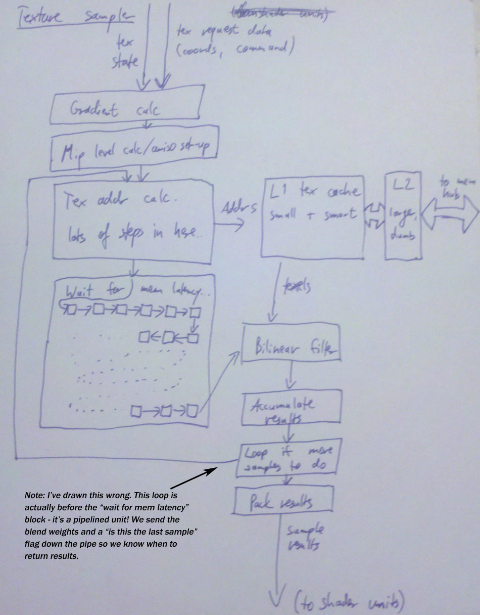
And that’s it – the shader unit now has its texture sampling results back and can resume working on the batch you submitted – which concludes this part. See you again in the next installment, when I talk about the work that needs to be done before we can actually start rasterizing primitives. Update: And here’s a picture of the texture sampling pipeline, including an amusing mistake that I’ve fixed in post like a pro!
The usual post-script
This time, no big disclaimers. The numbers I mentioned in the bandwidth example are honestly just made up on the spot since I couldn’t be arsed to look up some actual figures for current games :), but other than that, what I describe here should be pretty close to what’s on your GPU right now, even though I hand-waved past some of the corner cases in filtering and such (mainly because the details are more nauseating than they are enlightening).
As for texture L1 cache containing decompressed texture data, to the best of my knowledge this is accurate for current hardware. Some older HW would keep some formats compressed even in L1 texture cache, but because of the “1.25 misses/sample for a large range of cache sizes” rule, that’s not a big win and probably not worth the complexity. I think that stuff’s all gone now.
An interesting bit are embedded/power-optimized graphics chips, e.g. PowerVR; I’ll not go into these kinds of chips much in this series since my focus here is on the high-performance parts you see in PCs, but I have some notes about them in the comments for previous parts if you’re interested. Anyway, the PVR chips have their own texture compression format that’s not block-based and very tightly integrated with their filtering hardware, so I would assume that they do keep their textures compressed even in L1 texture cache (actually, I don’t know if they even have a second cache level!). It’s an interesting method and probably at a fairly sweet spot in terms of useful work done per area and energy consumed. But I think the “depack to L1 cache” method gives higher throughput overall, and as I can’t mention often enough, it’s all about throughput on high-end PC GPUs :)

Your whole series is very interesting, and filled with much more technical insight that one might expect.
“The above summary doesn’t even cover fun issues such as texture borders or sampling cubemap edges/corners. Trust me, it may sound bad now, but if you were to actually write out the code for everything that needs to happen here, you’d be positively horrified.”
Amen to that…
I’ve seen your demoscene experience, and you are now at RAD; you don’t seem to have worked at an IHV. Yet, I’m surprised by the depth of your knowledge on hardware, here. Who hinted you at nitty gritty details? Maybe Tom Forsyth, who worked on Larrabee. Anyone else?…
I’ll give you the highlights: I’ve been doing low-level systems/graphics programming for a while, with some compression and compiler work on the side. Some of my friends are GPU HW/SW architects in the embedded space (car navigational systems and such) so I’ve had a direct line to GPU architects well before I ever met Tom. :) In 2008 I got my degree and went to work in the games industry, doing all kinds of fun work, a lot of it being rendering/optimization work on PS3, Xbox 360 and Wii (sometimes all three at them at once; I needed an extra desk just to stack the Devkits…). Then Jeff hired me to work at RAD on Larrabee, where I arrived in spring 2010 just in time to get a thorough introduction and then a front-row seat for the fireworks (namely it being moved to HPC when all of our contacts at Intel where in the graphics group). So I ended up helping Sean get Iggy out the door, finishing the half-completed Xbox 360 port and writing new ports for PS3 and Wii, plus a D3D10 renderer on PC – with a lot of optimization work on the side. Meanwhile Intel decided they’d still like us to do some research work on graphics, which is what I’ve been doing for most of this year so far :)
Impressive…
I wish you could tell what research work you guys are doing. ;-)
Also, about your friends doing GPU HW/SW architecture for car navigators: are they doing shaders on those, these days? Somehow, I doubt they kept up with DX11-class pipeline AMD/NVIDIA have (Matrox couldn’t keep up), but sometimes, small teams can do impressive stuff…
Even the GL ES world is all on shaders these days. Hardware that targets 2D/OpenVG instead is more likely to still have a fixed function pixel pipe though (register combiner-style). Vertex shaders are a done deal though; a usable programmable vertex shader unit isn’t more complex (in either area, power draw or design/validation effort) than a compliant implementation of the OpenGL fixed-function vertex pipeline: there’s position/normal transformation, vertex lighting (for multiple lights!), materials, texture coordinate generation, color/texture matrix, all that crap. If you replace that with a vertex shader unit, you need all the math blocks once instead of multiple times (which is a net win); some buffers get replaced with a register file (more or less a wash), the sequencing/glue logic gets replaced with an instruction decoder/sequencer (a bit more complex so net loss) and validation effort goes from “we have to verify that this HW implements the fixed-function vertex pipeline correctly in all cases” down to “we have to verify that all the math blocks, the IO and the instruction decoder/sequencer work” (absolutely massive win!).
Actually the original HW implementations of OpenGL just used programmable SIMD arrays for both vertex and pixel processing. I’m not even sure whether early PC hardware T&L boards like the GeForce 256 actually implemented the vertex pipe fully in dedicated logic, or whether it was a custom vector processor/DSP that was microcoded. The latter seems more likely, and at that point going to a programmable pipe is a disruptive but incremental change.
Sure, described this way, VS is an easy switch. But how about efficient PS? I mean, when you open up IEEE-compliant floats, arbitrary shader length (as opposed to 4 texture combiners fixed-function stages), all of the specialized texture fetches, and other things, you end up opening quite a large verification door, I think. And power utilization is king in embedded land. So, if the fixed-function pipeline does the job, is it worth switching architecture?
Are you saying my TomTom could have better 3D capability than my iPod Touch 2nd generation? (OpenGL ES 1.1, not 2.0)
I was just talking about VS. I did mention that pixel processing for low-power devices (especially when they don’t need to run 3D games) is still doing register combiner-style stuff, and likely to stay that way. Going from a few 8-bit precision blend units to programmable shading is a big deal, and a losing move if your target apps don’t actually need it.
Hi Thanks for the article, I’ve been looking for something like this for a while.
Also, I wondering if you know how texture was store in video memory(especially 3D texture). I assume it would be some kind of block base scheme(Ziyad S. Hakura’s texture cache paper). I hope to get similar performance by implement my own tri-linear interpolation using linear memory(in cuda or openCL) instead of rely on 3D texture.
There’s no single answer to that question. Each GPU has its own preferred texture storage formats, which are usually different for 2D and 3D textures (and the array variants), and most GPUs also support multiple layouts for all of them. I didn’t go into detail on texture storage because I’ve written a blog post exclusively on this subject a few months ago (here) which talks about a general family of storage formats that is quite common. Most texture layouts I’ve seen in practice can be directly expressed within that scheme, and the ones that don’t can be closely approximated :).
Most current PC GPUs support linear formats, which are trivial. The various tiled formats vary a lot though. As for volume textures, I believe NVidia hardware used a straight Morton Order (aka Bit-Interleaving) layout for 3D textures at some point; I’m not sure if that’s still the case though, and I also have no clue what AMD uses for 3D textures.
Thanks a lot! That’s very helpful. I tried some simple tiling method before I read this, got about 40% of the 3D texture performance. There should be some space for optimization.
I’m really liking this series. It’s got the perfect level of info for somebody who wants to get seriously deep.
I do have one nitpick on this part, though:
“the answer is yes, we really have to (if we want anisotropic filtering that is)”
How do you think you can send down the u,v derivatives on non-PS shaders ? the whole x/y screen position you’re supposed to derive on is specific to PS.
All shader types can use
SampleGrad. “Sending down” the values is no problem at all – hey, it’s just a bunch of floats!I guess what you mean is how you’re supposed to derive them. Most obvious example first: you can do postprocessing filters using Compute Shaders too. Like in PS, your target has a natural cartesian 2D parmetrization. Unlike PS, you don’t get implicit derivative calculations, so if you want anisotropic filtering (and there’s good reasons to use aniso even for 2D processing, e.g. when your input and output buffers have different pixel aspect ratios) you need to use
SampleGrad. But it doesn’t have to derivatives in pixel coordinates; the derivative vectors you pass toSampleGraddefine a Jacobian matrix. Any sufficiently (locally) smooth mapping between two 2-dimensional spaces allows such a Jacobian to be computed, and anisotropic filtering does the “right” thing (in the sense of it being a typically good approximation of Heckberts Elliptical Weighted Averaging filter); there is still an approximation involved in determining filter shape from the Jacobian, and some more approximation in locally linearizing the approximation to place sample values.Anyway, there’s more common cases than don’t involve arbitrary smooth 2D maps; in particular, grid-based meshes have a natural 2D parametrization. For Vertex Shaders, you’d typically see grid meshes in e.g. height map-based rendering. Another place where meshes with a natural 2D parametrization crop up is with Tessellation (which I haven’t discussed yet), particularly on “quad” domains. If the patch control points form a grid, you get a natural parametrization in the Hull Shader (and hence also a pair of natural axes along which to compute derivatives or at least differences). Similarly, the Domain Shader for quad domains gets 2D U/V coordinates which is also a natural 2D parametrization. And of course you can play the same game in Geometry Shaders too.
Let me say thank you for writing this series. I find it very helpful to deepen my knowledge in graphics programming.
I’m wondering though, where does the number 1.25 misses/sample in the case of bilinear filtering come from ? Can you elaborate on that ?
This is just a really really coarse rule of thumb. Also, this is a bandwidth estimate (see below), which I should’ve made clearer in the post, not a statement about the absolute frequency of cache misses – that depends on the cache architecture.
Anyway, 1.25 texels/pixel. Short version: I’m gonna give you some rationale for why you would expect that number to be 1 per pixel or a bit more (in the bandwidth sense). I’m not gonna go into why 1.25; Honestly, I just got that number off people working on texture samplers and didn’t ask. But let’s start with why you would expect something
in the vicinity of 1 texel/pixel or more.
The mipmap level chosen per pixel is picked such that the texel-to-pixel ratio is as close to 1:1 as possible. Now, suppose that you’re filling the entire screen with a single quad using a repeating 512×512 RGBA8888 texture, at 1:1 scale. If your texture cache is anything smaller than 512x512x4 bytes = 1MB (they’re way smaller than that), the texture will not fit
entirely inside the cache.
Suppose for now that we access the entire texture before we get back to a location we’ve already referenced (I’ll get back to that in a minute). In that case, we will reference at least 1 “new” (not in the cache) texel for every pixel on the screen, more if we’re unlucky; and this has nothing to do with bilinear filtering per se, this will happen with any filter kernel (provided it’s the same filter footprint for every pixel). Why? Let’s look at a partially-rendered image (crappy ASCII art inbound):
‘#’ = pixel we finished earlier, ‘@’ = pixel we’re currently working on, ‘.’ = pixel we’re gonna look at later.
Now I’ve already said that for now, we’re assuming 1:1 texel:pixel mapping – so this picture looks the same if we plot texels we’ve accessed while rendering these pixels. Bilinear is a 2×2-tap kernel, so we sample 4 positions. Out of those 4, 3 are positions we already accessed while rendering the adjacent pixels (which happened “recently”). The fourth (the bottom right of the 4 pixels) is “new” and hasn’t been accessed since we last accessed the texture.
This is hand-wavey, but I want to give you a mental picture of the process. A slightly more rigorous view is just that we’re streaming 1MB of data through, say, a 32k cache. With 1:1 pixel scaling and point sampling (no bilinear), we just access one texel per pixel, and that’s a texel we haven’t accessed “in a long time” so it’s not in the cache. As we make the filter kernel bigger (and better), the number of texels accessed per pixel increases linearly, but the number of “new” texels accessed does not. We may access more texels earlier than before, but we’re still accessing the same texels eventually (is it clear why? If not, I can give more examples). Now if you keep growing the filter footprint at some point this will stop working as your footprint becomes large enough not to fit in the texture cache by itself, but that’s not a problem for usual texture sampling filters. :)
Anyway. I was assuming before that the texel data falls out of the cache before we reference it again, despite using a repeating texture. Is that really true? Well, it depends. You might get lucky in some cases, but it’s pretty much true in general; textures tend to be big. You gain a lot from making your texture caches large enough that texels hang around between shading for most adjacent pixels when rasterizing. Then it plateaus pretty soon until the cache is large enough to contain entire the entire texture working set for a shader.
For the sake of argument, let’s say that our texture is stored in linear (raster-scan order), and we render strictly top to bottom, left to right. In that case, we might not even need the full texture cache! If we’re rendering to a 2048×1024 screen (rounded from 1920×1080 for convenience), we get 4 repeats of the 512×512 texture per scan line, and it only takes (512×4)x2 = 4kb to store the 2 scan lines worth of texture that are actually accessed while rendering this scan line! So we get 4x reuse from the texture cache after all!
Well, not quite. Because now I’m gonna be mean and start slanting the texture coordinates (even when I perform a slant, it’s still a 1:1 mapping in terms of density – the determinant of a slant is 1, and the amount of memory accessed should not change, just the order). Enough so that, by the point we’ve moved 512 pixels to the right, we’ve also moved 128 texel rows down in the texture. And now the 4 copies of the texture access texels distant enough from each other that (with our raster-order rasterization pattern) they’re only gonna be in the cache by the next time we come around if the cache is large enough to contain the whole texture.
Actual GPUs do not rasterize in scan-line order, and they do not (by default) store textures in raster order; they use traversal patterns and layouts optimized for 2D access, to make sure that all orientations work roughly equally well. These make the worst cases better and the best cases worse. That’s good – predictable latency you can easily design around, covering high variability is trickier since it leads to bursty behavior.
This covers 1:1 mappings. You can’t get arbitrarily far from there – mip map selection will pick something reasonable, assuming that is that there are actually mip maps present and in use. But yes, if you were to zoom in, you’d access fewer unique texels per pixel; if you were to zoom out, you’d access more. At which point it’s more handwaving – in general, you have about as many texels overshooting their target mip level than undershooting it, and so forth. But it gets pretty spotty at that point.
Okay, that gives us a very rough intuition for why 1 texel/pixel is reasonable. Why more?
Well; triangles have edges; caches have set conflicts; real scenes have tons of textures and several batches; and so forth. What this all presumes is
a long steady state where we’re merrily shading a large triangle, and the only real limit is cache capacity. So 1 is definitely optimistic. Why use an extra fudge factor of 0.25 instead of something else? I don’t know, and I’m not gonna pretend I do. :)
Extra caveats: a) as said before, this is just a rule of thumb, b) it’s also only valid for large textures and in the statistical sense (i.e. as average over longer periods of time), c) this is a statement about texture memory access bandwidth (throughput) not latency. What I’ve been saying here assumes that texels are cached individually. That is, of course, not the case in practice; texel caches are organized in terms of lines, same as other caches. Say we’re sticking with the 4byte/pixel RGBA8888 format, and we have 64-byte cache lines. That means we have 16 texels per cache line. If the memory layout is good, we will thus get 16 texels per cache miss, and these are actually 16 texels that we will all want (sooner or later). Thus, we have only 1/16th the number of texture cache misses in terms of “how many texture accesses try to read from a line that’s not currently in the cache”. But the overall amount of memory we access is still the same: 1/16th the number of misses that now fetch 16x the data. And if the texture layout is not good (or doesn’t match our access patterns), we might fetch 64 bytes worth of texels but only actually use 16 bytes from that cache lines, because the other 48 bytes are for texels we don’t care about – this is always a risk when making cache lines bigger.
Okay, now suppose that we have 64-byte cache lines (with 16 texels/line at RGBA8888), but our texture sampler also processes 16 bilinear sampling requests per cycle (FWIW, both of these values are, as of this writing, realistic). Now, even assuming good texture caching, we’re back at 1 cache miss/cycle (or worse); we’re processing 16 pixels, with our larger cache lines roughly 1/16th of all pixels processed should miss the cache, and so we’d expect about 1 missed cache line per cycle.
Note that I can make the figure of “how many cache misses per cycle” go up and down by tweaking these values: halve the number of pixels processed per cycle – tada, half the cache misses! Double the cache line size – halved again! But note that to render our screen-filling quad, we still have the same number of texels accessed and read roughly the same amount of memory.
That’s why the bandwidth number (number of memory read per pixel) is more useful as a general reference than any per-clock number; it’s not as sensitive to architectural details, and it’s also more relevant to one of the actual bottlenecks in GPUs (namely, memory bandwidth).
Thank you for explaining it in great detail, and the caveats as well. I have to say that I somehow thought that the texels were cached individually :p
Fabian, thanks for this awesome series of articles. I was just referred back to this by a coworker after many years, and it sparked a pretty in-depth discussion.
I don’t know if you’d still update this article, but it would’ve saved us a few hours of debate :)
You say:
“But this means that, unless you happen to hit the exact same location in a texture again and again, each texture sampling operation will miss about 1 texel on average – the actual measured value with bilinear filtering is around 1.25 misses/request (if you track pixels individually). ”
Only in the comments section you correct:
“Also, this is a bandwidth estimate (see below), which I should’ve made clearer in the post, not a statement about the absolute frequency of cache misses”
You should make it explicit in the original article that the 1 texel/request figure is actually just a lower bound on the *bandwidth* requirements, and remove the reference to “cache misses”, or clarify it. The 1.25 figure is an empirical estimate, at best, and, as you point out, you have no solid theoretical justification to back it up. So it should be made explicit that it’s an empirically sourced number. The theoretical lower bound on bandwidth is 1 texel/request for point or bilinear filtering.
You can construct scenarios where the cache miss frequency is much higher or lower than 1 miss per request (usually much lower with tiling/swizzling), and you can construct pathological scenarios with linear memory layouts at 90 degrees to each other where the actual bandwidth requirements are multiples of this lower bound due to throwing away most of the data in cache lines you fetch and have to re-fetch (as you also point out in the comments), but you can’t ever get *below* this lower bound on bandwidth, as long as you maintain close to 1 texel per pixel density.
I don’t think my prose is very concise or intelligible as is, but I’m sure you could make the original article more intelligible, and maybe save future readers a bit of headache, as this still is a de facto reference several years on! :)
Keep up the good work!
Steve
Nowhere do I say that 1.25 is a lower bound. It’s not. I’m talking about texture-sampling induced memory bandwidth (memory accesses) not number of texel requests. The lower bound is 0 (not quite, but you can get arbitrarily close) and occurs when you have a tiny texture (let’s take a trivial example, a 2×2 texture) that fits fully within the sampler L1 caches. Consider the case where you’re drawing a million batches with that one texture. If the texture fits inside the sampler caches, there will be no more requests all the way to memory after the cache lines containing the data were initially loaded, no matter how much you draw with it. Hence the limit of memory requests per texel sampled goes to zero (since you can increase the number of texels sampled arbitrarily without increasing the number of cache misses).
At the opposite extreme, the upper bound for texel misses per bilinear texture sample is 4 per pixel evaluated. A texture fetch/sample is fundamentally a “gather” style operation, and knowing sufficient details about the caches and texture tiling patterns, you can construct a worst-case pattern where *not a single texel fetched* is ever inside the L1 or L2 caches at the time when it’s requested. A bilinear fetch grabs 4 texels and you can in fact arrange for none of them to ever hit the cache.
In practice, your texture is typically way too large to fit inside your sampler caches, and texture memory accesses have reasonable locality of reference and temporal locality. Under these conditions and with mip mapping enabled the number of texel misses per pixel will usually be close to the 1.25 I state (though this is really just a rule of thumb). Without mip mapping (or with a large negative mip map LOD bias) it’s actually really easy to hit the worst case of 4 texels per pixel.